How to effectively use the TFN FB18 Cable Fault Detector in power construction?
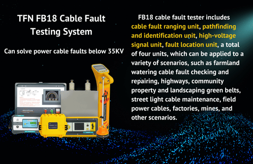
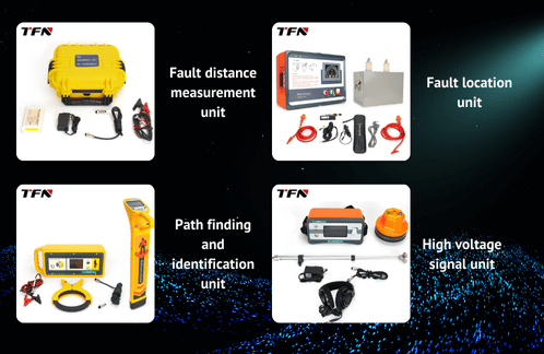
Cable faults are a common problem in power construction and operation and maintenance. Quickly and accurately locating the fault point can significantly shorten power outages. As an integrated professional device, the TFN FB18 Cable Fault Detector integrates four core components: a distance measuring unit, a path finder, a locator, and a high-voltage signal generator. It can systematically troubleshoot various cable faults up to 35kV. Below, we'll detail its practical application process in power construction, combining its features.
1. Fault Pre-Location: Accurate Distance Measurement (Rough Measurement) with the Distance Detector
The distance measuring unit is the first step in troubleshooting, used to determine the nature of the fault and its approximate distance range.
1.1. Method Selection:
Low-Resistance/Open-Circuit Faults: Use the "Low-Voltage Pulse Method" directly. Attach the unit's clamps (red clamp to the faulty phase, black clamp to the cable armor ground wire). After powering on the unit, select "Low-Voltage Pulse" mode and click "Sample" to capture the waveform. Use the waveform start and reflection point cursors to directly read the distance.
High-resistance faults: Use the "Impact High-Voltage Flashover Method" in conjunction with high-voltage equipment. Connect the high-voltage generator, energy storage capacitor, and ball gap. Place a current sampler near the cable ground wire and connect it to the main unit. Select the "Flashover Method" mode on the main unit, click "Sampling," and wait for the high voltage to strike the fault point. Obtain the flashover waveform and interpret the distance.
1.2. Key Operation Points:
Set Cable Type/Velocity: Select the appropriate type based on the cable insulation medium (cross-linked vinyl, oil-impregnated paper, etc.). If the type is unknown, use the "Velocity Measurement" function to measure the velocity of a known length of cable to ensure distance accuracy (system accuracy <50cm).
Adjust Pulse Width/Accuracy: Select an appropriate pulse width (0.05μs-8μs) based on the estimated fault distance. Pulse width affects the test distance and reading resolution (1m-8m).
Waveform Analysis/Saving: Use "Waveform Zoom" and "Scroll" to observe details, and use "Auto Distance Detection" or manual cursor positioning. Save typical waveforms promptly for later comparison.
Tips: The distance measurement result of the host is a "rough measurement" and needs to be used with a positioning device for precise positioning. During construction, the ground distance often differs from the measured distance due to the winding of underground cables.
2. Path Tracing: A path finder accurately locates cable path
For buried cables (especially those with unknown paths), a path finder (consisting of a transmitter and receiver) is key to determining their path and depth.
2.1. Signal Application Method Selection:
Preferred Direct Connection Method: Suitable for de-energized cables. Connect the red clamp of the transmitter to the target cable core, and reliably ground the black clamp separately (away from the cable). Frequency options include 577Hz or 82kHz. This method provides strong signals, long transmission distances, and excellent interference resistance.
Secondary Coupling Method: Suitable for exposed points on live or de-energized cables. Use a coupling clamp to clamp onto the cable. 82kHz is recommended. This method is particularly suitable for detecting live paths.
Induction/Blind Testing: Suitable for cables with no exposed points and depths less than 10m. Place the transmitter above a known point, align the test lead with the cable path, and select a frequency of 82kHz or 133kHz (high power). Blind testing (surface/point testing) can reveal unknown pipelines.
2.2. Receiver Tracking Techniques:
Power on the receiver and select the same frequency as the transmitter. The peak method (wave crest) is typically used.
Start near the signal application point (avoiding the ground electrode) and adjust the gain until the signal strength is around 500-800.
Maintaining the gain, rotate the receiver to find the point where the signal is strongest and the direction is stable. The direction the receiver is pointing indicates the cable's path. Follow the direction of the strongest signal to determine the precise path.
Stand the receiver firmly above the path (with the receiver pointing forward) to directly read the depth and current values. Alternatively, use the 80% method to verify depth.


3. Precise Fault Location: The locator locks onto the fault location.
Based on the approximate range defined by the distance measuring unit and the path determined by the path finder, the locator is responsible for the final, precise targeting of the fault point.
3.1. Acoustic-Magnetic Synchronous Pinpointing Method (Common):
Applicable to high-resistance flashover faults. Connect an acoustic-magnetic probe (pickup + induction coil).
High-voltage equipment continuously strikes the fault point, generating periodic discharges.
Select the "Acoustic-Magnetic Pinpointing" mode (continuous or single shot) on the locator. Move the probe close to the ground along the path.
Fault Location Characteristics:
A clear "crackling" sound synchronized with the discharge (loudest at the point of discharge) is heard in the earphones.
On the display: The electromagnetic signal bar illuminates (synchronized with the sound), and the distance display is minimized (close to 0m).
The waveform area displays repetitive characteristic sound waves. Single shot mode allows for detailed analysis of waveform details and the distance axis.
Enabling intelligent noise reduction suppresses ambient noise and reduces auditory fatigue.
3.2. Step Voltage Method (A-Frame):
Suitable for low-resistance faults caused by cable sheath damage or direct ground leakage from the core wire.
Connect the red clamp of the transmitter to the faulted phase, and the black clamp to a separate ground connection (away from the test area). Frequency: 577 Hz (high power).
Switch the locator to "Step Voltage" mode and connect the A-frame.
Insert the two pins of the A-frame into the soil approximately 1 meter apart along the cable path (or on either side).
Observe the waveform changes on the screen: Before the fault point, the waveform amplitude is large and the initial direction is consistent; directly above the fault point, the waveform amplitude is minimum (close to zero); after passing the fault point, the waveform amplitude increases again, but the initial direction is in the opposite direction. The point of inversion is the fault point.
4. Key Points for Construction Safety and Efficiency
4.1. High Voltage Safety is a Red Line:
When using a high-voltage signal generator, it must be reliably grounded! The ground wire should be connected directly to a capacitor ground or a dedicated ground stake to prevent ground potential rise and damage to the equipment.
At least two people are required for this operation, and wiring must be strictly inspected. During the impact test, the rangefinder must be disconnected from the external AC power supply and operate only with the internal battery.
After the test, the discharge probe must be discharged first, and then the ground wire must be connected. Only after confirming that the capacitor voltage is zero can the wire be removed.
4.2. Equipment Collaboration and Setup:
When performing high-voltage flashover testing on the ranging host, always select the "Flashover Method" mode. Inadvertently selecting the "Low-Voltage Pulse" mode can cause equipment short circuit damage.
When performing blind testing on a path finder, maintain a distance of approximately 7 meters between the receiver and transmitter and adjust the gain to the baseline value (approximately 500). This balances detection depth and blind spots.
When the locator battery is low, recharge it promptly to avoid data loss or interruption of operation.
4.3. Combining Environment and Experience:
In complex environments (strong interference, multiple parallel cables), try different frequencies and modes (peak/valley) for path detection, and use the diagram as a guide for judgment.
If the acoustic and magnetic signal is weak during locating, try changing the locator's filter band (low frequency band is suitable for soft soil/muffled sound, high frequency band is suitable for hard road surface/loud discharge).
Conclusion
The TFN FB18 cable fault tester, through the coordinated operation of four major components, provides a comprehensive solution for power construction projects, from fault distance measurement, path location, to precise location. Mastering its core functions—waveform analysis for the distance measuring unit, blind measurement and tracking techniques for the path finder, acoustic-magnetic synchronization and step voltage determination for the locator—while strictly adhering to high-voltage safety regulations, can significantly improve cable fault troubleshooting efficiency, shorten construction power outage windows, and ensure reliable grid operation.
