How does the TFN GP200 optical cable survey instrument identify the target optical cable?
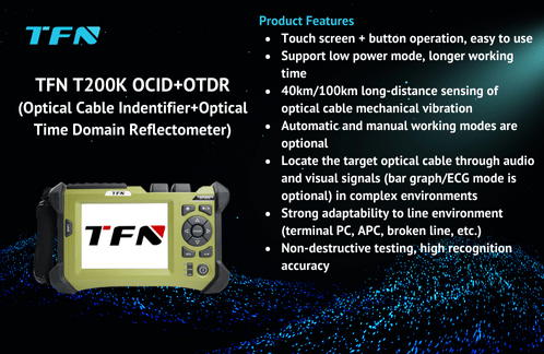
The optical cable identifier (OCID) is a device that uses acoustic principles to accurately find and identify the target optical cable. It is designed for telecommunications engineers or technicians. Its working principle is based on fiber interference technology. The percussion vibration signal of the optical cable is converted into visual and audio signals through coherent demodulation of light, thereby achieving accurate positioning of the optical cable. The TFN GP200 series optical cable identifier (referred to as "GP200") integrates the functions of the optical cable identifier and OTDR. This article mainly introduces how the GP200 identifies the target optical cable and precautions.

The following are the operating steps for the GP200 to identify the target optical cable:
1. Place the device stably
Place the GP200 on the working platform of the machine room. If there is no platform, ensure that it is placed stably.
2. Determine the type of measurement jumper interface
According to the type of flange connector on the optical cable patch panel under test, select the appropriate measurement jumper interface, and ensure that the measured jumper and the GP200's OCID (enhanced optical cable census instrument) connection port type are both FC/APC connectors to ensure smooth connection. At the same time, the other end of the jumper must also match the flange connector interface type on the optical patch panel.
3. Clean each connection port
Use a cleaning tool to clean the OCID output port (FC/APC) and the measurement jumper ceramic connector separately to ensure that there is no dust or impurities. Then align the measurement jumper with the instrument output port flange and connect it, and clean the ceramic connector at the other end of the measurement jumper again. During the connection process, please pay attention to properly preserve the ceramic connector protective cover.
4. Connect the optical cable
After connecting the OCID to the measurement jumper, connect the jumper to the flange on the optical cable patch panel under test. Please note that the types of each connection interface must match.
5. Turn on the power and select the test module
Press the POWER button to turn on the power, connect the headphones to the audio output port of the instrument, and select the OCID test module on the home page.
6. Set the target optical cable end length
Click the "Line Settings" button, click the "Test" button on the "Line End Settings" page, move the trace icon bar to the line end position or directly manually enter the measured optical fiber length. After the setting is completed, return to the OCID test page.
Note: In the optical fiber line end setting test mode, after the test is completed normally, the target optical cable link length value will be automatically entered into the dialog box; if the test is stopped early during the test, the automatically entered length value of the link length may be inaccurate.
7. Verify that the connection is normal
Click the "Test" button on the OCID test page and tap the measurement jumper connected to the GP200. If the image amplitude changes significantly on the OCID LCD screen, confirm that the measurement jumper is connected normally; then connect the jumper to the flange on the optical cable distribution frame under test, and gently tap the optical cable behind the distribution frame with a tapping stick or other metal tools. If the image jumps significantly, confirm that the flange connection is normal.
8. Handle the isolation of the target optical cable at the tapping point
The near-end engineer notifies the on-site engineer to separate the multiple optical cables at the tapping point. It is best to remove the bundling point, untie the original bundled optical cable bundle by at least 1 meter, tap the optical cable at a distance of more than half a meter from the bundling point with appropriate force, and number each optical cable with tape. If the bundle is too tight, the tapping will cause vibration conduction and affect the measurement effect. Use sponge or isolation tape to isolate the optical cable to reduce resonance during tapping. The same effect can be achieved by having one person hold the optical cable with both hands and another person tapping the optical cable.
9. Test and confirm the target optical cable
On the OCID test page, click "Test" to start. The near-end engineer first determines the target optical cable from the ECG image: when the field engineer taps the optical cables one by one, the instrument has almost no response to other optical cables. When the target optical cable is tapped, the ECG or intensity bar display mode on the instrument LCD panel will reflect the intensity of the optical cable line vibration signal, and the image will show a relatively obvious intensity fluctuation consistent with the tapping amplitude/frequency; confirm the correctness of the target optical cable again from the audio headset. Press the "Stop" key to end the test.
Note:
Tap intensity: Tap the optical cable gently to initially determine the target optical cable position from the ECG display video mode, then increase the tapping intensity, and confirm that the determined target optical cable is correct through the tapping sound in the headset. If the knocking force is too weak, the on-site engineer needs to knock on each optical cable. The near-end engineer can hear a weak knocking sound in the headset, indicating that the vibration is too weak. The optical cable number that cannot hear the knocking sound is recorded, and then the on-site engineer is informed to gradually increase the knocking force, check the optical cables one by one, and accurately find the target optical cable to be measured.
Knocking frequency and rhythm: The on-site engineer should knock at a fixed rhythm frequency interval, and it is recommended to knock once per second so that the near-end engineer can distinguish.
Knocking point selection: It is recommended that the knocking point be as close to the instrument end as possible to ensure the test quality. For example, when the A and B machine rooms are 40km apart, if the knocking point is 10km away from A and 30km away from B, the instrument should be placed in the A machine room.
Enhanced end reflection: If the end reflection of the target optical cable is very weak, it is recommended to enhance the end reflection to improve the signal-to-noise ratio.
In addition, in the OCID function test, some issues need to be noted:
What is crosstalk?
Crosstalk refers to the phenomenon that vibration is transmitted from one optical cable to another. Therefore, if the optical cables are in too close contact, vibration may be transmitted from one optical cable to another, causing misidentification. It is recommended to separate the optical cables.
How to identify and eliminate small crosstalk signals?
Small crosstalk signals often do not cause obvious audio and video indications of the instrument. However, to ensure the measurement effect, it is recommended to separate the optical cables. If it is inconvenient to separate, it is recommended to use spiral acoustic isolation pads to isolate them to minimize crosstalk.
What tools can usually be used to knock on the optical cable?
Generally, small and easy-to-carry metal tools such as steel wrenches and screwdrivers are selected.
What is the appropriate position for the knocking point?
In the manhole or machine room, if the optical cables are bundled together, it is strongly recommended to separate them. Otherwise, large or small crosstalk will inevitably occur. At this time, the two measurement engineers at the near end and on-site should maintain telephone communication to ensure that the knocking force is appropriate and adjust the appropriate sensitivity for identification.
What kind of force should be used to knock?
The force should be heavy at first to confirm that the optical cable is at the position to be tested, and then gradually reduce the force until no crosstalk is generated, so that the optical cable can be accurately identified.
If the optical cable is broken in the middle, can it be tested and how to test it?
At this time, depending on the degree of damage at the broken cable, it depends on the specific situation to determine whether it can be tested. Usually, an OTDR is used to find the breakpoint and observe whether the reflection at the tail end is large enough. If the reflection is large, it can be measured; if the reflection is small, it is more difficult to measure. Perform knocking measurements on the optical cable with optical fiber inside.
Can the instrument be used to find the pigtail? What should be paid attention to?
It can be found. Although this instrument is an enhanced optical cable census instrument, its main function is to find optical cables, but it can also be used for pigtails that meet the test conditions. However, it should be noted that one end of the pigtail to be checked must be connected to the instrument, so the pigtail cannot be measured online.

In short, GP200 can perform well in the process of optical cable maintenance, can quickly locate the target optical cable and detect the fault point of the optical cable. Its user-friendly interface, simple and practical, non-toxic and harmless, and no damage to the optical cable are deeply favored by engineers. Whether it is in manholes, tunnels, pipelines or overhead poles, GP200 can greatly improve the efficiency of optical cable repair and maintenance, and reduce the cost of engineering construction and management.
If you are interested in TFN GP200 series optical cable identifier, please contact TFN sales team:
Email: info@tfngj.com
WhatsApp: +86-18765219251
Facebook: https://www.facebook.com/tfnfate/
