Cable Fault Tester Waveform Analysis and Location Techniques
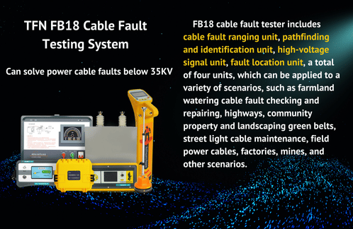
With the rapid development of urban power grid construction, underground power cable transmission and distribution lines have gradually replaced overhead lines and become the main component of urban distribution networks. However, due to the hidden cable laying, fault troubleshooting has become particularly difficult. As a highly efficient and accurate detection tool, the cable fault tester can quickly determine the fault location through waveform analysis and location techniques to ensure the normal operation of the power supply system.
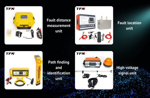
The cable fault tester mainly performs waveform analysis based on the pulse reflection method (i.e., flash test method). When a cable fails, the tester sends a pulse signal to the cable, which is transmitted in the cable and reflects when encountering different wave impedance points (such as the fault point). By analyzing the characteristics of the reflected waveform, the fault type and location can be determined. The following will introduce the waveform analysis and positioning techniques of the cable fault tester in detail.
1. Waveform analysis method
Low-voltage pulse method: mainly used to test open circuit or broken line faults. The waveform characteristics are that the transmitted pulse is a positive pulse waveform, and the reflected waveform may be a positive pulse or a negative pulse, depending on the cable state and the test method. When testing the full length or measuring the speed, the waveform is relatively regular, and the spacing between each reflected waveform is consistent. When setting the cursor, the starting point of the cursor is set at the intersection of the rising edge of the transmitted pulse and the baseline, and the end point is selected according to the positive and negative nature of the reflected waveform. The intersection of its rising edge or falling edge and the baseline.
High-voltage flashover method: suitable for testing high-resistance faults. Under high-voltage shock, when the fault point is broken down, a voltage wave with opposite polarity will be generated, forming a complex reflected waveform. The cursor positioning method is similar to the low-voltage pulse method, but it should be noted that the waveform may be more complex, and the waveform characteristics need to be carefully analyzed to determine the cursor position.
Secondary pulse method: It is an efficient method that releases a high-voltage pulse to cause a flashover at the fault point, and triggers the release of a second low-voltage pulse at the same time. The two received low-voltage pulse reflection waveforms are superimposed, and the position of the bifurcation point is the fault point position. This method greatly simplifies waveform analysis and improves the speed of fault handling.
2. Waveform feature analysis
Open circuit fault waveform: After the first fault point reflection pulse, there are several reflection pulses with a distance equal to the fault distance. This is the result of the pulse reflecting back and forth between the measuring end and the fault point many times. Be careful not to mistake the subsequent reflection pulses for the reflection pulses of other fault points.
Short circuit fault waveform: The pulse polarity after the first fault point reflection pulse changes alternately from positive to negative. This is because the reflection coefficient of the pulse at the fault point is -1, while the reflection at the measuring end is positive.
Low resistance fault waveform: The injected pulse generates a reflection pulse at the fault point, which is reflected many times between the measuring end and the fault point. The distance between the second fault point reflection pulse and the first fault point reflection pulse is the fault distance.
3. Positioning skills
Ensure measurement accuracy
When performing waveform analysis and calibration, the accuracy and stability of the measuring equipment should be ensured to avoid introducing additional errors.
Correctly select the test method
Select the appropriate test method according to the specific type and nature of the cable fault. For example, a multimeter can be used to directly measure direct short circuit or disconnection faults; a megohmmeter can be used to test insulation resistance for indirect short circuit and ground faults.
Pay attention to waveform characteristics
During the waveform analysis process, the characteristics of the waveform should be carefully observed, such as the polarity, amplitude, shape of the waveform, and the spacing between each reflected waveform. These characteristics are crucial for determining the type and location of the fault.
Combine with other test methods
When the waveform analysis is difficult to determine the fault location, other test methods such as the bridge method, capacitance current measurement method or zero potential method can be combined for comprehensive judgment.
Pay attention to safety
When conducting cable fault testing, the safety operating procedures should be strictly followed to ensure the safety of personnel and equipment. In particular, when using high-voltage equipment for testing, necessary safety protection measures should be taken.
4. Other auxiliary technologies
Acoustic detection method: discharge the faulty cable through a high-voltage pulse generator, and an arc and discharge sound are generated at the fault point. In the case of direct cable burial, seismic waves are generated, and the seismic wave signal is picked up by the acoustic detection probe of the positioning instrument and amplified and output. This method is suitable for high-voltage cables, low-voltage cables, direct buried cables, etc.
Acoustic magnetic synchronization method: the acoustic detection method and the electromagnetic wave method are combined, and the positioning is carried out by combining the acoustic detection method positioning method with the acoustic magnetic synchronization positioning method. This method can distinguish the weak acoustic wave signal of the fault point in a noisy environment and improve the positioning efficiency.
Magnetic field predetermined point technology: an arc is generated at the fault point of the cable through a high-voltage DC pulse generator, and an audio signal is injected into the cable. A dedicated receiver is used to receive the audio electromagnetic wave signal radiated by the cable. By comparing the changes in the amplitude of the audio electromagnetic wave before and after the fault point, it is judged that the receiver is before or after the fault point, so as to achieve the purpose of rapid predetermined point.
Therefore, the waveform analysis and positioning skills of the cable fault tester need to comprehensively consider multiple factors and methods. By mastering waveform analysis methods such as low-voltage pulse method, high-voltage flashover method and secondary pulse method, combined with waveform feature analysis and positioning skills, as well as the application of auxiliary technology, the cable fault point can be found quickly and accurately to ensure the normal operation of the power supply system. At the same time, strengthening the basic data management of the operating power cable lines, improving the cable route map, the cable line electronic geographical distribution map, etc., is very helpful for quickly finding cable faults.


If you are interested in TFN cable fault locator system, please contact TFN sales team:
Email: info@tfngj.com
WhatsApp: +86-18765219251
Facebook: https://www.facebook.com/tfnfate/
